Blog

Home

Blog

  • Types of Control Valves and Applicable Conditions of Common Control Valves
    Types of Control Valves and Applicable Conditions of Common Control Valves
    Jun 04, 2022
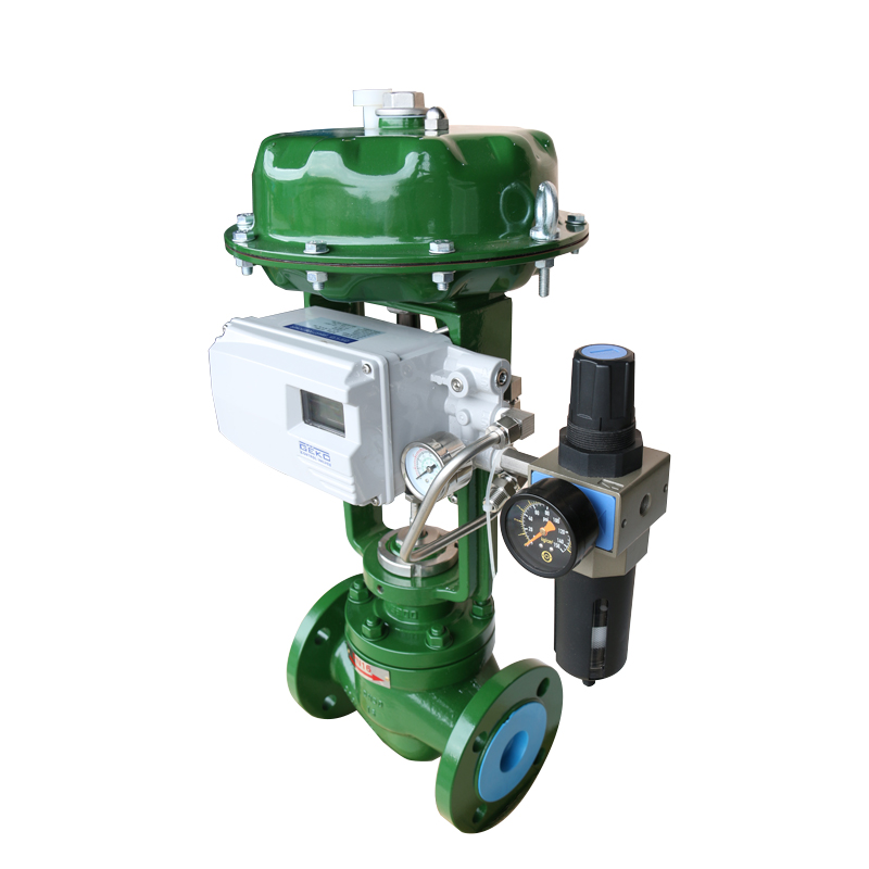
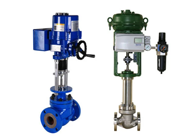
    According to different use requirements, there are many types of control valves, which can be divided into straight stroke and angular stroke according to the way the valve core moves; Diverter three-way control valve, confluence three-way control valve, diaphragm valve, etc.; can be divided into on-off type, integral type and proportional type according to the action law; Close the valve. Only a few commonly used control valves are briefly introduced here.   1. Straight-through single-seat control valve   The straight-through single-seat control valve type has only one valve core and one valve seat in the valve body, simple structure, small leakage (even completely cut off), small allowable pressure difference, suitable for clean media requiring small leakage and small working pressure difference the occasion. In the application, special attention should be paid to the allowable pressure difference to prevent the valve from closing.   2. Straight-through double-seat control valve   The straight-through double-seat control valve has two valve cores and valve seats in the valve body. Because the force of the fluid on the upper and lower spools can cancel each other, the straight-through double-seat control valve has the characteristics of large allowable pressure difference, and the upper and lower spools are not easy to close at the same time, so the leakage is large. It is suitable for clean medium occasions with large pressure difference between both ends of the valve and low leakage requirements, but not suitable for high viscosity and fiber-containing occasions.   3. Angle control valve   The valve body of the angle control valve is a right angle, with a simple flow path and low resistance. It is suitable for the control of high pressure difference, high viscosity, suspended solids and granular substances. Angle control valve is generally suitable for bottom in and side out. At this time, the control valve has good stability. In the case of high pressure difference, in order to prolong the service life of the valve core, side in and bottom out can also be used. However, the side in and the bottom out are prone to shock when the opening is made. Angle valves are also suitable for applications where process piping is right-angle piping.   4. Three-way control valve   The valve body of the three-way control valve has three connecting ports, which are suitable for the pipeline control system of the fluid in three directions, and are mostly used for temperature adjustment, ratio adjustment and bypass adjustment of heat exchangers. In use, it should be noted that the fluid temperature difference should not be too large, usually less than 150 °C, otherwise the three-way control valve will be deformed due to large stress, resulting in leakage or damage to the connection. There are two types of three-way control valve: confluence three-way valve and split three-way control valve. The confluent three-way control valve has two input ports for the medium. After flowing in and mixing, it flows out through an outlet; the split three-way control valve is for the medium to flow in from an inlet, and it is divided into two outlets to flow out.
    Read More
  • Maintenance Method of Key Inspection Parts of Control Valve
    Maintenance Method of Key Inspection Parts of Control Valve
    Jun 04, 2022
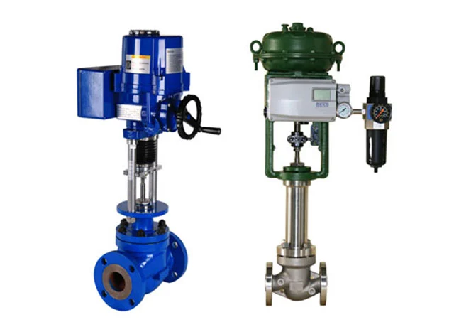
    The control valve is the actuator in the automatic control system, and its application quality is directly reflected in the adjustment quality of the system. As a terminal element in process control, people have a newer understanding of its importance than in the past. The quality of the control valve application, in addition to the quality of the product itself, whether the user is correctly installed, used, and maintained, it is very important to calculate and select correctly. Due to the error of calculation and selection, the system starts and stops, and some even cannot be used. Therefore, users and system designers should recognize the importance of valves on site, and must pay enough attention to the selection of control valves.   The control valve has the characteristics of simple structure and reliable action, but because it is in direct contact with the process medium, its performance directly affects the quality of the system and environmental pollution, so the control valve must be regularly maintained and repaired, especially for harsh and important operating conditions. On occasion, more attention should be paid to maintenance work of inspection sites.   1. Maintenance of the inner wall of the control valve   For control valves used in high pressure difference and corrosive media, the valve body wall and the diaphragm of the diaphragm valve are often impacted and corroded by the medium, and the pressure and corrosion resistance must be checked.   2. Maintenance of control valve seat   When the control valve is working, due to the infiltration of the medium, the inner surface of the thread used for fixing the valve seat is easily corroded and the valve seat is loosened, so attention should be paid during inspection. For valves that work under high pressure difference, it is also necessary to check whether the sealing surface of the valve seat is damaged.   3. Maintenance of control valve spool   The valve core is a movable part during adjustment work, and it is most seriously eroded and corroded by the medium. During maintenance, it is necessary to carefully check whether the various parts of the valve core are corroded and worn, especially in the case of high pressure difference. The wear of the valve core is more serious. (Due to cavitation), attention should be paid. When the valve core is seriously damaged, it should be replaced. In addition, attention should be paid to whether the valve stem also has a similar phenomenon, or the connection with the valve core is loose.   4. Maintenance of control valve diaphragm   "O" rings and other gaskets. Check whether the diaphragm and "O"-shaped gasket in the control valve are aging and cracked.   5. Maintenance of control valve sealing packing   Pay attention to whether the PTFE packing and sealing grease are aging, and whether the mating surface is damaged, and should be replaced when necessary.   The control valve is the main type of actuator, which changes the fluid flow by power operation by receiving the control signal output by the regulating control unit. Control valves generally consist of actuators and valves. According to the power used by its equipped actuator, the control valve can be divided into three types: pneumatic, electric and hydraulic, namely the pneumatic control valve using compressed air as the power source, the electric control valve using electricity as the power source, and the liquid medium (such as oil) pressure-driven hydraulic control valve, in addition, according to its function and characteristics, there are solenoid valve, electronic, intelligent, fieldbus control valve and so on.
    Read More
  • How to Use Manual Ball Valve?
    How to Use Manual Ball Valve?
    Jun 04, 2022
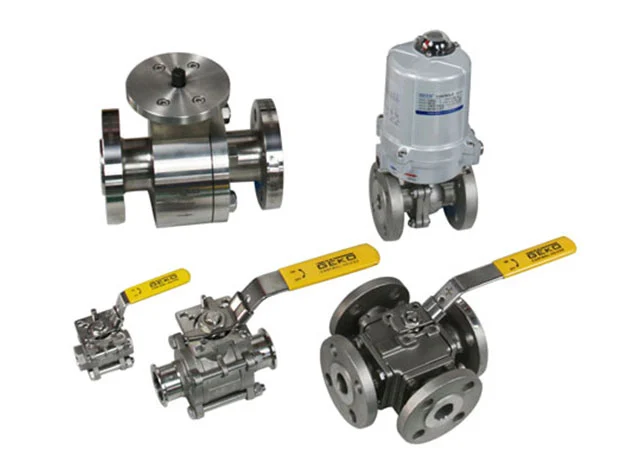
    Stainless steel manual ball valve and gate valve are the same type of valve, the difference is that the closure is a sphere, and the sphere rotates around the center line of the valve body to reach an open and closed valve. Ball valves are mainly used for blocking, distributing and changing the moving direction of the medium in the pipeline. Stainless steel manual ball valve is a relatively new type of ball valve. It has some advantages unique to its own structure, such as no friction in the switch, not easy to wear the seal, and small opening and closing torque. This reduces the size of the fitted actuator. Equipped with multi-reversal electric actuators, it can realize the adjustment and tight interception of the medium. It is widely used in petroleum, chemical, urban water supply and drainage and other working conditions that require strict blocking.   1. Structural characteristics of stainless steel manual ball valve   (1) Friction-free opening and closing: completely solve the problem that the traditional valve affects the sealing due to the friction between the sealing surfaces.   (2) Top-loading structure: The valves installed on the pipeline can be directly inspected and repaired online, which can effectively reduce installation and parking and reduce costs. Manual ball valves should generally be installed horizontally in the pipeline.   (3) Single valve seat design: eliminates the problem that the medium in the cavity of the valve affects the safety of operation due to abnormal pressure increase.   (4) Low torque design: The valve stem with special structure design can easily open and close the valve with only a small handle.   (5) Wedge-shaped sealing structure: the valve is sealed by the mechanical force supplied by the valve stem, which presses the ball wedge onto the valve seat to seal, so that the sealing performance of the valve is not affected by the change of the pressure difference of the pipeline, and the sealing function is under various working conditions. All are guaranteed.   (6) The self-cleaning structure of the sealing surface, when the sphere tilts away from the valve seat, the fluid in the pipeline passes evenly along the sphere sealing surface at 360°, which not only eliminates the local scouring of the valve seat by the high-speed fluid, but also washes away the sealing surface. On the accumulation, to achieve the purpose of self-cleaning.   2. Principle and usage of manual ball valve   The working principle of stainless steel manual ball valve: stainless ball valve relies on rotating the valve core to dredge or block the valve. The ball valve is easy to switch, small in size, can be made into a large diameter, reliable in sealing, simple in structure, and convenient in repair.   (1) Open process   In the closed position, the ball is pressed on the valve seat by the mechanical pressure effect of the valve stem. When the handwheel is rolled counterclockwise, the valve stem moves in the opposite direction. Lift, and interact with the guide pin in the spiral groove of the valve stem, so that the ball starts to rotate without friction until it reaches the full open position, the valve stem is lifted to the limit position, and the ball rotates to the full open position.   (2) closed process   When closed, rotate the handwheel clockwise, the stem of the manual ball valve begins to descend and the ball is separated from the valve seat and begins to rotate; if the handwheel is continuously rotated, the stem is affected by the guide pin embedded in the upper spiral groove, so that the stem and the ball At the same time, it rotates 90°. When it is about to close, the ball has rotated 90° without contacting the valve seat. During the last few turns of the handwheel, the angular flat at the bottom of the valve stem mechanically wedges the ball to press it tightly against the valve seat to achieve a complete seal.
    Read More
  • What Are the Structural Classifications of Gate Valves?
    What Are the Structural Classifications of Gate Valves?
    Jun 04, 2022
    There are many different ways to classify the gate valve structure, the main difference is the different structural forms of the sealing elements used. According to the structure of the sealing element, the gate valve is often divided into several different types, and the most common gate valve types are parallel gate valve and wedge gate valve. According to the structure of the valve stem, it can also be divided into rising stem gate valve and dark stem gate valve.   1. Parallel gate valves   The two sealing surfaces of the parallel gate valve are perpendicular to the axis of the pipeline, that is, the gate valve with the two sealing surfaces parallel to each other. Among the parallel gate valves, the structure with a thrust wedge is the most common, and the parallel gate valve is suitable for low pressure, medium and small diameter valves. The spring can generate the necessary pre-compression force, which is beneficial to the sealing of the gate. In addition, there are parallel gate valves with mechanical devices (such as levers, screw mechanisms, etc.) to push the gate open, and one-way parallel gate valves with only one sealing pair. These structures are currently only used under special working conditions.   2. Wedge gate valves   The two sealing surfaces of the wedge gate valve form a certain angle with the axis of the pipeline, that is, the gate valve in which the two sealing surfaces are wedge-shaped. The size of the inclination angle mainly depends on the temperature of the medium. Generally, the higher the working temperature, the larger the angle should be to reduce the possibility of wedging of the gate when the temperature changes. In the wedge gate valve, it can be divided into double gate, single gate and elastic gate.   3. Rising stem gate valves   The valve stem nut of this kind of gate valve is set on the valve cover or bracket. When opening and closing the valve, the valve stem nut is rotated to realize the lifting and lowering of the valve stem. In this structure, the threaded part of the valve stem is not in contact with the medium, and is not easily corroded by the medium, and at the same time is beneficial to the lubrication of the threaded part of the valve stem, so it is widely used. Contact GEKO, a professional gate valve supplier, for the gate valve price.   4. Dark stem gate valves   The valve stem nut of this kind of gate valve is in direct contact with the medium in the valve body. When opening and closing the valve, it is realized by rotating the valve stem. The only advantage of this structure is that the height of the gate valve does not change when opening and closing, so the gate valve installation space is small. However, this type of valve must be equipped with an opening and closing indicator to display the opening of the valve.   At present, in petroleum and chemical systems, especially in long-distance oil and natural gas pipelines, flat gate valves with floating valve seats are widely used. This kind of flat gate valve has low fluid resistance, reliable sealing performance and long service life. This type of gate valve is divided into guide holes and without guide holes. The flat gate valve with diversion hole is mainly used in oil and natural gas pipelines to clean the pipeline, and the flat gate valve without diversion hole is suitable for opening and closing devices on various pipelines. The manufacturing process of this gate valve is relatively simple, and it is easy to realize automatic production.
    Read More
  • Gate Valve Installation and Maintenance Precautions
    Gate Valve Installation and Maintenance Precautions
    Jun 04, 2022
    The handwheel, handle and transmission mechanism are not allowed to be used for lifting, and collision is strictly prohibited. Double-gate gate valves should be installed vertically (i.e. the stem is in the vertical position and the handwheel is on top). The gate valve with the bypass valve should open the bypass valve before opening (to balance the pressure difference between the inlet and the outlet and reduce the opening force). The gate valve with transmission mechanism shall be installed according to the provisions of the product instruction manual. If the valve is used frequently, lubricate it at least once a month. The gate valve is used as a cut-off medium. When fully open, the entire flow is straight, and the pressure loss of the medium is minimal at this time. Gate valves are usually suitable for conditions that do not require frequent opening and closing, and keep the gate fully open or fully closed.   1. The gate valve is not suitable for use as regulation or throttling   For high-speed flowing media, the gate can cause vibration of the gate when it is partially opened, and the vibration may damage the sealing surface of the gate and the valve seat, and the throttling will cause the gate to be eroded by the medium. From the structural form, the main difference is the form of the sealing element used. According to the form of the sealing element, the gate valve is often divided into several globe valves types , such as: wedge gate valve, parallel gate valve, parallel double gate valve, wedge double gate gate valve, etc. The most common forms are the wedge gate valve and the parallel gate valve.   2. Matters needing attention when using the gate valve disc   The function of this type of valve is to allow the medium to flow in only one direction, and to prevent flow in one direction. Usually this kind of valve works automatically. Under the action of fluid pressure flowing in one direction, the valve flap opens; when the fluid flows in the opposite direction, the fluid pressure and the self-coincident valve flap of the valve flap act on the valve seat, thereby cutting off the flow. Among them, the check valve belongs to this type of valve, which includes swing check valve and lift check valve. Swing check valves have a hinge mechanism and a door-like disc that rests freely against the sloping seat surface. In order to ensure that the valve disc can reach the proper position of the valve seat surface every time, the valve disc is designed in the hinge mechanism, so that the valve disc has enough swing space and makes the valve disc truly and comprehensively contact the valve seat. Discs can be made entirely of metal, or inlaid with leather, rubber, or synthetic overlays, depending on the performance requirements.   According to the conditions of use, the disc can be of all-metal structure, or it can be in the form of a rubber pad or rubber ring embedded on the disc holder. Like the globe valve, the passage of fluid through the lift check valve is also narrow, so the pressure drop through the lift check valve is larger than that of the swing check valve, and the flow of the swing check valve is limited rare.   In the production process, in order to make the pressure, flow and other parameters of the medium meet the requirements of the technological process, it is necessary to install an adjustment mechanism to adjust the above parameters. The main working principle of the adjustment mechanism is to achieve the purpose of adjusting the above parameters by changing the flow area between the valve disc and the valve seat. These valves are collectively referred to as control valves, which are divided into self-propelled control valves that rely on the power of the medium itself, such as pressure reducing valves, pressure-stabilizing valves, etc.) is called other-driven control valve, such as electric control valve, pneumatic control valve and hydraulic control valve, etc.
    Read More
  • What Are the Commonly Used Non-metallic Valve Materials?
    What Are the Commonly Used Non-metallic Valve Materials?
    Jun 04, 2022
    1. Nitrile rubber valve material   Nitrile rubber valve materials are rated for temperatures ranging from -18°C to 100°C. It is an excellent general purpose rubber material for water, gas, oil and grease, gasoline (except gasoline with additives), alcohol and glycol, LPG, propane and butane, fuel oil and many other media. At the same time, it also has good wear resistance and deformation resistance.   2. Ethylene propylene rubber valve material   The rated temperature range of the ethylene propylene rubber seat is -28°C~120°C. Excellent ozone resistance and weather resistance, good electrical insulation performance, good resistance to polar solvents and inorganic media. Therefore, it can be widely used in HVAC industry, water, phosphate ester, alcohol, glycol, etc. Ethylene-propylene rubber seats are not recommended for use in hydrocarbon organic solvents and oils, chlorinated hydrocarbons, turpentine or other petroleum-based greases.   3. PTFE valve material   The rated temperature range of PTFE industrial valve material is -32℃~200℃. Excellent high temperature resistance and chemical corrosion resistance. Because PTFE has high density and excellent anti-permeability, it can also prevent corrosion from most chemical media. Conductive PTFE is a modified version of PTFE that allows current to pass through the lining thereby eliminating the insulating properties of PTFE. Because of its conductive properties, conductive PTFE cannot be tested for its quality by electric sparks.   4. Fluorine rubber valve material   The rated temperature of the fluororubber seat is -18°C~150°C. This material has high temperature resistance and excellent chemical resistance. Suitable for hydrocarbon products, low and high concentrations of mineral acids, but not for steam media and water (poor water resistance).   5. UHMWPE valve material   The rated temperature range of UHMWPE valve material is -32℃~88℃. This material has better low temperature resistance than PTFE, but still has excellent chemical resistance. Ultra-high molecular weight polyethylene also has good wear resistance and corrosion resistance, and can be used in high abrasive situations.   6. Silicon copper rubber valve material   Silicon-copper rubber is a polymer with organic groups whose main chain is composed of silicon-oxygen atoms. The rated temperature range is -100℃~300℃. It has good heat resistance and temperature resistance, excellent electrical insulation performance and high chemical inertness. Suitable for organic acid and low concentration inorganic acid, dilute alkali and concentrated alkali.   7. Graphite valve material   Graphite valve material is a crystal of carbon, a non-metallic material with silver-gray color, soft texture and metallic luster. It has unique physical and chemical properties such as high temperature resistance, oxidation resistance, corrosion resistance, thermal shock resistance, high strength, good toughness, high self-lubricating strength, strong thermal conductivity and electrical conductivity. It has special oxidation resistance, self-lubrication and plasticity at high temperature, and also has good electrical conductivity, thermal conductivity and adhesion. It can be used as a filler or performance improver for rubber, plastic and various composite materials to improve the wear resistance, compression resistance or conductivity of the material. Graphite is usually used to make valve gaskets, packing and valve seats.
    Read More
  • Where is the Electric Triple Eccentric Butterfly Valve Mainly Suitable for Use?
    Where is the Electric Triple Eccentric Butterfly Valve Mainly Suitable for Use?
    Jun 04, 2022
    At this stage, the electronically controlled triple eccentric butterfly valve is mainly aimed at a regulating machine for flow. At present, because the pressure loss of the butterfly valve in the pipeline is relatively large, of course, in addition to the above, it should also be considered that the butterfly plate needs to bear a medium pressure of the pipeline when it is closed. In addition, the operating temperature of the elastic valve seat material also needs to be considered in the case of high temperature.   1. High sealing packing structure of triple eccentric butterfly valve   On the leakage problem of the valve, traditionally, the leakage of the valve seat is often concentrated, that is, the internal leakage, and the leakage of the packing part, that is, the external leakage, is ignored. In fact, in the contemporary society where environmental issues are increasingly valued, it has become an indisputable fact that external leakage is far more harmful than internal leakage. The triple offset butterfly valve is a rotary type valve, and its stem action is only 90 ° rotation. Compared with gate valve, globe valve and other valve stem action with spiral multi-turn reciprocating motion, the wear degree of the packing part is very low. The service life is very long, and the highest standard design is adopted in the external leakage prevention structure such as packing seal, so that the standard sealing performance can be guaranteed to be less than 100ppm when the external leakage test is carried out according to the specifications.   2. Three eccentric butterfly valve refractory structure   Many valves claim to have a fire-resistant construction, but the vast majority of them use a soft-hard dual-seat construction to reduce leakage, which can be dangerous. Because the incomplete combustion of the soft-sealed valve seat during a fire will cause stress on the metal support valve seat and deformation due to temperature difference, resulting in failure of the refractory function. Therefore, currently Europe and the United States are gradually eliminating this kind of refractory valve that does not live up to its name. This ensures that it can be used in various hazardous areas such as petroleum, petrochemical and so on. In the conservative United Kingdom, the valves used in all key parts of its oil fields are almost all covered by butterfly valves, which is the best example.   3. Application occasions of triple eccentric butterfly valve   At present, the structural length and overall height of the valve body are relatively small, the opening and closing speed is relatively fast, and it also has some characteristics of fluid control. The structure principle of the butterfly valve is mainly suitable for the manufacture of large-diameter valves. And when the butterfly valve is required for flow control, the size and model of the butterfly valve should be correctly selected to ensure that the butterfly valve can work correctly and efficiently.   In the process of throttling, regulating and mixing the medium with mud, the main requirements are that the length of the structure is short and the speed of opening and closing is fast. At present, the pressure difference of low pressure cut-off is relatively small. At this stage, it is recommended to choose a triple eccentric butterfly valve for adjustment and maintenance. And in two-position adjustment, narrowing channel, low noise, cavitation, gasification, a small amount of atmospheric leakage, and abrasive media can choose butterfly valve. At present, for the main throttling adjustment under special working conditions, tight sealing is required. Maybe when the butterfly valve is used under severe wear and low temperature (cryogenic) conditions, a specially designed metal sealing belt adjustment device is required, using triple eccentric or double eccentricity. Eccentric special butterfly valve.
    Read More
  • How to Choose the Valve in the Water Supply Network?
    How to Choose the Valve in the Water Supply Network?
    Jun 04, 2022
    The water supply network is composed of various pipe accessories and fittings such as pipes and valves. According to various needs (water volume of the pipe network, scheduling and deployment of water pressure, water stoppage for maintenance and repair, connection of old and new pipelines, flushing of pipelines, etc.), the valve must be opened and closed every day. The service life and quality of the valve determine the normal operation of the pipe network and play a pivotal role in the pipe network, which must be given great attention. Since the pipe network is a bridge between water supply enterprises and the vast number of users, it can be said that the quality of a water supply enterprise's management work is reflected in the normal operation of the pipe network; and the normal operation of the water supply pipe network is related to the valve. Life and quality are closely related.   1. Reliability of valve quality   The quality of the valve is reflected in the whole process of valve manufacturing. There must be a more complete quality assurance system. The indicator of the number of times the valve is switched on and off is of little significance, and it does not necessarily have to meet the test of more than 5,000 times of switching. Because the valves in the pipe network are not frequently opened and closed. Sometimes, some valves only open once every ten years. In actual work, we found that the positioning screws on the butterfly valve are loose during installation, and some have no bolt threads at all.   2. Flexibility of valve operation   It is important that high-quality valves operate flexibly. Flexible operation is not only reflected in which transmission mode is selected, but also in the machining accuracy of the components related to the transmission mechanism. For example, in the transmission mode of the butterfly valve. There are generally two transmission methods: screw nut type and worm gear type. The general lead screw nut type is characterized by slow opening and closing at both ends and fast in the middle, which is easier to operate. However, due to the small torque of the lead screw, it is difficult for the operator to grasp the degree of opening and closing of the valve plate during operation, and it is easy to occur that the valve is closed and the valve is closed. Still operating twists and breaks the lead screw. The worm gear type is generally easy to close the position. At the same time, the sealing of the valve stem of the gate valve and the matching of the rotational speed and torque of the butterfly valve transmission part are the long-standing and difficult problems of valve operation. Therefore, the choice of transmission mode should be based on the situation of each water supply enterprise, after listening to the operator's opinions, and closely cooperate with the manufacturer, so that the selected valve can not only operate flexibly, but also meet the needs of use and work.   3. Reasonability of valve price   Valves should have a reasonable price, and a reasonable price is not necessarily the lowest price. If you only focus on the lowest price, it is easy to mislead manufacturers in order to promote their products, compete to lower the price, or even sell them below the cost price of the product. In order not to lose money, manufacturers must cut corners on processes and materials, and the valves produced exist. Due to the hidden quality problems, when it is used in the water supply network, the ultimate victim is the user himself. Therefore, we must pay attention to when choosing high-quality valves, encourage manufacturers to use the principle of value engineering, strengthen main functions, remove redundant functions, and optimize system functions. Work hard on management and work hard on cost accounting. It should be noted that a reasonable price can be the lowest price, but the lowest price is not necessarily a reasonable price.   4. Guarantee of valve after-sales service   When the valve is used in the water supply network, there will be such and other problems, some of which belong to the valve itself, and some are caused by interference and damage from external factors, brutal construction, illegal operation, and poor management and use. But no matter what the reason, the valve problem will affect the operation of the pipeline network, which requires the cooperation of the valve maker. Therefore, the valve manufacturer needs to have a good after-sales service guarantee when selecting the valve. Once there is a problem with the valve, we can rush to the scene in the shortest time and solve the problem as soon as possible.
    Read More
  • The Adam’s MAK Series and the GEKO GKV9 Series Triple Offset Butterfly Valves are fully interchangeable
    The Adam’s MAK Series and the GEKO GKV9 Series Triple Offset Butterfly Valves are fully interchangeable
    Jun 04, 2023
    In the world of industrial valves, the compatibility and interchangeability of valve components are of paramount importance. Engineers and professionals frequently seek valve solutions that offer flexibility and versatility while maintaining high performance. In this regard, the GEKO GKV9 Series and Adam’s MAK Series Triple Offset Butterfly Valves stand out as remarkable options. These valves are engineered to be fully interchangeable, allowing for seamless integration of components and valves between the two series. This article explores the impressive compatibility between the Adam’s MAK and GEKO GKV9 Series Triple Offset Butterfly Valves.   GEKO GKV9 Series Triple Offset Butterfly Valves: The GEKO GKV9 Series Triple Offset Butterfly Valves are renowned for their exceptional performance and durability. Designed with three eccentric offsets, they offer zero leakage, excellent throttling capabilities, and extended service life. These valves are widely used in various industries, such as oil and gas, chemical, and power generation, where precise and reliable flow control is essential.   Adam’s MAK Series Triple Offset Butterfly Valves: The Adam’s MAK Series Triple Offset Butterfly Valves are another top-tier solution for flow control applications. These valves are constructed with precision and engineered for high-performance service in challenging environments. The MAK Series is recognized for its resilience, exceptional sealing properties, and optimal flow control capabilities. Like the GEKO GKV9 Series, they find application across industries with stringent requirements.   Interchangeability: One of the most remarkable features of these valve series is their interchangeability. The GEKO GKV9 Series and Adam’s MAK Series have been designed to have compatible parts and components. This means that valve operators and engineers can easily replace or upgrade their existing valves with components from either series without any compatibility issues. This interchangeability streamlines maintenance, reduces downtime, and provides cost-effective solutions for valve-related requirements.   Benefits of Interchangeability:   Flexibility: The ability to interchange components between the GEKO GKV9 and Adam’s MAK Series provides engineers and operators with greater flexibility when designing or maintaining their systems. They can choose the best valve for specific applications while ensuring that replacements or upgrades can be made effortlessly.   Reduced Downtime: Downtime in industrial operations can be costly. Interchangeability minimizes downtime as replacements can be quickly installed, reducing the impact on production schedules.   Cost-Effective: The interchangeability of these valves results in cost savings. There is no need to invest in an entirely new valve system when components can be easily swapped out or upgraded.   Consistency and Reliability: Both valve series offer outstanding performance and reliability. When components are interchangeable, it ensures consistent performance across a system, minimizing the risk of compatibility issues and enhancing overall reliability.   The compatibility and interchangeability of GEKO GKV9 Series Triple Offset Butterfly Valves with Adam’s MAK Series Triple Offset Butterfly Valves represent a significant advancement in valve technology. This feature provides engineers, professionals, and industries with greater flexibility, reduced downtime, and cost-effective solutions for their flow control needs. As these valves continue to evolve and gain prominence in various industries, their interoperability is a testament to the commitment to engineering excellence and customer-focused solutions.  
    Read More
  • Geko Assisted the Construction and Operation of the ±800KV UHV DC Line from Baihetan Power Station to Jiangsu
    Geko Assisted the Construction and Operation of the ±800KV UHV DC Line from Baihetan Power Station to Jiangsu
    Jun 04, 2022
    On July 1, 2022, State Grid Corporation of China Baihetan-Jiangsu ±800 kV UHV DC project (referred to as "Baihetan-Jiangsu Project") was completed and put into operation. It is understood that the completion and commissioning of the Baihetan-Jiangsu project is a specific action of the State Grid to implement the decisions and deployments of the Party Central Committee and the State Council, adding another energy artery across the country from east to west, which is crucial for optimizing energy allocation, ensuring power supply, stimulating economic growth, Promoting green development and leading technological innovation have significant comprehensive benefits and long-term strategic significance. It is reported that the Baihetan-Jiangsu project is a key project to ensure power supply during the peak season, a major project to stabilize economic growth and promote development, a green project to serve the "double carbon" goal, and a technologically independent electric ball valve innovation project.   1. The implementation of large-scale "West-to-East power transmission" and "North-to-South power supply" UHV DC lines is a major strategy for energy development   After the Baihetan-Jiangsu project is completed, it can effectively guarantee the large-scale delivery of Baihetan Hydropower Station, promote the transformation of Sichuan's resource advantages into economic advantages, and help the economic rise of the western region. The project can add 4 billion to 6 billion kWh of surplus hydropower in Fengqi, Sichuan every year, greatly improving the efficiency of hydropower utilization. At the same time, the Baihetan-Jiangsu project is the second Sichuan Power into the Su-Su special high-voltage project after the Jinping-Sunan UHV project. The electric ball valve UHV DC line has a power transmission capacity of 8 million kilowatts, which can meet Jiangsu's economic Social development and people's electricity needs for a better life. The project cooperates with the existing UHV project in East China to increase the proportion of clean energy consumption in Jiangsu, enhance the power grid's ability to help each other with water and fire, help meet the peak summer and winter peaks, and effectively alleviate the mid-to-long-term contradiction between power supply and demand in East China.   The Baihetan-Jiangsu ±800 kV UHV DC project was completed and put into operation, which will also promote environmental protection and help the construction of a beautiful city. After the Baihetan-Jiangsu project is completed and put into operation, it will deliver over 30 billion kWh of clean electricity every year, which will help East China to reduce coal consumption for power generation by 14 million tons, carbon dioxide emissions by 25 million tons, sulfur dioxide by 250,000 tons, and nitrogen oxides by 220,000 tons. Significantly improve the environmental quality in East China, promote the green transformation of Jiangsu's energy, and win the battle to defend the blue sky.   2. Baihetan Jiangsu Project is the world's first UHV DC line with hybrid electric ball valve   For the first time in the world, the hybrid cascaded UHV DC transmission technology of "conventional DC + flexible DC" has been developed, integrating the advantages of large capacity, long distance, low loss of UHV DC transmission, flexible control of flexible DC transmission, and strong system support capabilities. Leading by example is of great significance. The electric ball valve UHV DC line project developed 20 new equipment such as controllable self-restoring energy dissipation devices, large-capacity single-column converters, and amplitude and phase correctors for the first time. Among them, the controllable self-restoring energy dissipation device can quickly achieve millisecond-level energy balance, greatly improving the power receiving capacity of the East China Power Grid. After the project is completed and put into operation, Yucheng Converter Station will become the first converter station in the world to adopt conventional DC and flexible DC mixed-level connection lines.
    Read More
  • Difference Between PFA Lined Valves and PTFE(teflon) Lined Valves
    Difference Between PFA Lined Valves and PTFE(teflon) Lined Valves
    Jun 04, 2023
    PFA (Perfluoroalkoxy) lined ball valves and PTFE (Polytetrafluoroethylene) lined ball valves are both types of lined valves designed to handle corrosive and aggressive media. While they share similarities, there are key differences between the two in terms of material properties and performance characteristics.     Material Composition:   PFA Lined Ball Valves : PFA is a type of polymer that is similar to PTFE(teflon). It exhibits high chemical resistance and a broad temperature range. PFA lining is often used in ball valves to protect against corrosion and enhance the valve's performance in aggressive environments.   PTFE(teflon) Lined Ball Valves: PTFE is another fluoropolymer with excellent chemical resistance. PTFE lined ball valves use a lining made of PTFE to provide a barrier between the corrosive media and the valve's internal components.     Temperature Resistance:   PFA Lined Ball Valves: PFA generally has a higher continuous-use temperature compared to PTFE. This makes PFA lined ball valves suitable for applications involving elevated temperatures.   PTFE Lined Ball Valves : PTFE can withstand a broad range of temperatures but may have limitations in high-temperature applications compared to PFA.   Flexibility:   PFA Lined Ball Valves: PFA is known for its flexibility, allowing for easy lining of complex shapes. This flexibility can be advantageous in the manufacturing of valves with intricate designs.   PTFE Lined Ball Valves: PTFE is also flexible, but PFA may be preferred in applications where a high degree of flexibility is critical.     Chemical Resistance:   PFA Lined Ball Valves : Both PFA and PTFE exhibit excellent chemical resistance, but PFA may offer slightly better resistance to certain chemicals in specific applications.   PTFE Lined Ball Valves : PTFE is widely recognized for its exceptional chemical inertness, making it suitable for handling a broad range of corrosive substances.   Cost:   PFA Lined Ball Valves: PFA is generally considered a more expensive material compared to PTFE. Therefore, PFA lined ball valves may be more costly.   PTFE Lined Ball Valves: PTFE is a widely used and cost-effective material, making PTFE lined ball valves a more economical option in some cases.   In summary, while both PFA lined ball valves and PTFE lined ball valves are designed for corrosive applications, the choice between them depends on specific operating conditions, including temperature requirements, chemical exposure, and budget considerations. PFA lined ball valves may be preferred in high-temperature applications, while PTFE lined ball valves are known for their broad chemical resistance and cost-effectiveness.   If you need any of PFA PTFE PEP Teflon lined valves, please contat us now: info@geko-union.com!  
    Read More
  • How to Select ISO 12944 Coating Systems for Valves in different environment?
    How to Select ISO 12944 Coating Systems for Valves in different environment?
    Jun 04, 2023
    How do you correctly choose a coating system for your valves? With the extensive content of ISO 12944, how can you determine which environment your product falls into among C2, C2, C3, C4, C5, CX, lm1, lm2, lm3, lm4? Users mention that the coating's service life must reach 15 years—how do GEKO control valves prove this, and so on? To address these questions, GEKO control valves have summarized them into the ISO 12944 4S method for reference.   The 4S method is as follows: Step 1: Confirm the corrosion category (ISO 12944-2). Step 2: Confirm the durability of the protective coating (ISO 12944-1). Step 3: Select the coating system required for the project (ISO 12944-5). Step 4: Coating system laboratory validation (ISO 12944-6, optional).     Detailed description is as follows:   1) Confirming Corrosion Category (ISO 12944-2) The atmospheric environment is divided into six atmospheric corrosion categories: C1: Very low corrosion (Very low) C2: Low corrosion (Low) C3: Medium corrosion (Medium) C4: High corrosion (High) C5: Very high corrosion (Very High) CX: Extreme corrosion (Extreme)     Immersed in water or buried in the soil is divided into 4 categories: Im1: Freshwater Im2: Seawater or slightly brackish water without cathodic protection Im3: Soil Im4: Seawater or slightly brackish water with cathodic protection   2)Confirming the durability of protective valve coatings (ISO 12944-1) The standard specifies four different durability ranges: Low (L): Not exceeding 7 years Medium (M): 7-15 years High (H): 15-25 years Very high (VH): >25 years The durability of protective valve coatings is not a "guarantee period." The guarantee period is usually shorter than the durability, and there are no rules specifying the relationship between these two times. The "environmental type" and the "durability of the coating system" are the main parameters for selecting a coating system and must be given attention.     3)Selecting the Coating System Required for the valve Project (ISO 12944-5 or ISO 12944-9 in CX Environment) Based on the substrate, choose the minimum recommended coating system as per the standard. The coating systems in the standard are determined based on field application experience and laboratory performance test results according to ISO 12944-6. They provide valuable references. An example is the C2 table as shown below:     Points to Note:   1.The listed systems have been proven effective in practice, but it's not possible to list all coating categories. Other similar systems may also be feasible.   2.Under a given substrate type, coating performance can vary significantly depending on the specific composition of the coating. The substrate types described in Chapter 6 are just examples, and other types of valve coatings can also be used.   3.New technologies are constantly evolving and are often influenced by government regulations. Technologies proven effective through the following methods are acceptable:   a) After the application of these new technologies, tracking and recording verify their effectiveness.   b) Laboratory test results meet at least the requirements of ISO 12944-6 and ISO 12944-9.     4. Valve Coating System Laboratory Validation (ISO 12944-6) or Pre-Certification of Coating Systems (ISO 12944-9) In accordance with the standards, select a coating system. If the owner requires laboratory testing, the coating system must undergo laboratory testing, primarily based on ISO 12944-6 or ISO 12944-9. If your coating is a new technology, laboratory validation is necessary.   Step 1: Confirm the corrosion category (ISO 12944-2)   In this case, the valve project is located in a coastal industrial area, typically associated with energy, petroleum, and chemical industries. The environment is characterized by high humidity, high salinity, and high corrosion. Therefore, the selected environmental type based on the table is C5.     Step 2: Confirming the durability of protective valve coatings for project (ISO 12944-1)   The design service life is 20 years. According to the table, the selected range is 15 years to 25 years, so the durability choice is "High" (in practice, the durability of many valve coatings may also consider the construction cycle, typically assumed to be around 2 years).     Step 3: Select the coating system required for the valve project (ISO 12944-5)   The substrate of the sample is carbon steel, the environment is C5, and the durability is "High." Therefore, GEKO control valves choose to refer to Table B.1 and B.2 in Appendix C of ISO 12944-5, selecting coating systems for carbon steel under corrosion category C5. Specifically, ISO 12944-5/C5.03 or ISO 12944-5/C5.07 may be suitable.     Step 4: Coating System Laboratory Validation (ISO 12944-6, optional)   Conduct experimental tests to validate the selected coating system. This step may not be necessary if the user agrees to use the system recommended by the standard. However, if there is a desire to reduce potential disputes in the contract, testing confirmation can be performed before signing or periodic inspections can be conducted during the mid-project phase to ensure project quality.     According to ISO 12944-6, the testing items for C5-H are as follows:     After testing three panels, two of them meet the standard requirements, and it is deemed as compliant.   If you are looking for a reliable control valve ( Liquid, gas, powder) supplier for your project, please don’t hesitate to contact us: info@geko-union.com!  
    Read More
1 2 3 4 5
A total of5pages

leave a message

leave a message
If you are interested in our products and want to know more details,please leave a message here,we will reply you as soon as we can.
submit

home

products

contact