Exploring the Rotary Globe Control Valve: Design, Structure, and Applications
Jan 09, 2026
Comprehensive Guide to the Rotary Globe Control Valve: Design, Structure, and Applications. Discover the design, structure, and applications of the Rotary Globe Control Valve. Learn how this high-precision valve ensures optimal flow control in industries such as chemical processing, oil & gas, and HVAC.
Introduction
The Rotary Globe Control Valve is a vital component in fluid control systems, offering precise regulation of flow, pressure, and temperature. With its superior design and versatility, this valve has become a go-to solution across various industries, including chemical processing, oil & gas, water treatment, and HVAC. In this article, we will explore the design, structure, and applications of the Rotary Globe Control Valve, and how it contributes to optimized flow control.
Design of the Rotary Globe Control Valve
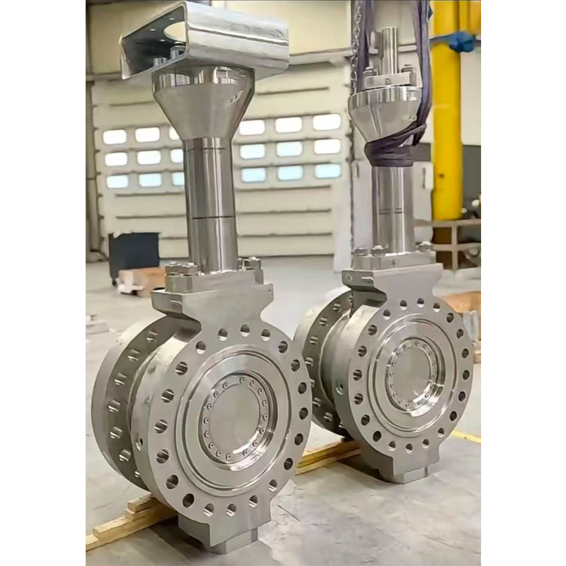
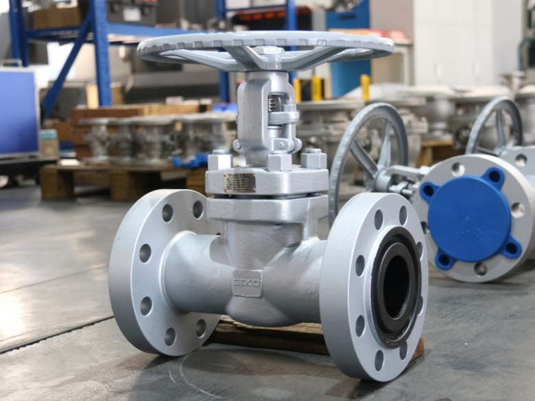
The Rotary Globe Control Valve combines the best features of both rotary and globe valves to offer a unique design that enhances precision and performance. The valve uses a rotary motion to control fluid flow, which is known for its smooth, consistent movement. This design provides an advantage in applications that require fine adjustments and highly accurate control over flow rates.
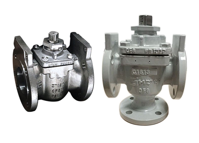
Rotary Motion: The valve’s body typically has a rotary valve plug or ball that rotates to open or close the valve, allowing for smooth control of flow.
Precision Adjustment: This valve offers high accuracy in flow regulation, making it ideal for precise applications such as chemical processing, where small changes in flow can have a significant impact.
Flow Path Design: The flow path inside the valve is designed for minimal resistance, ensuring that fluids move smoothly without turbulence or obstruction.
Structure of the Rotary Globe Control Valve
The Rotary Globe Control Valve is structured with several critical components that work together to ensure optimal performance and durability. These components include:
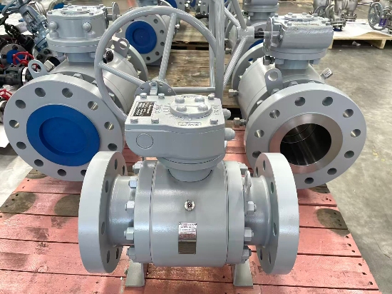
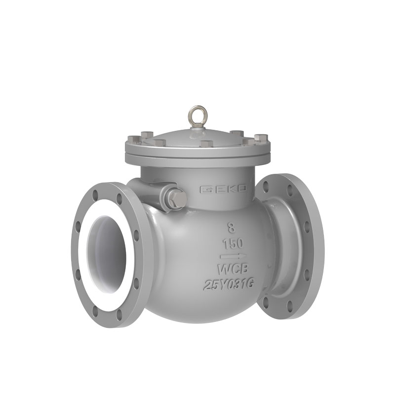
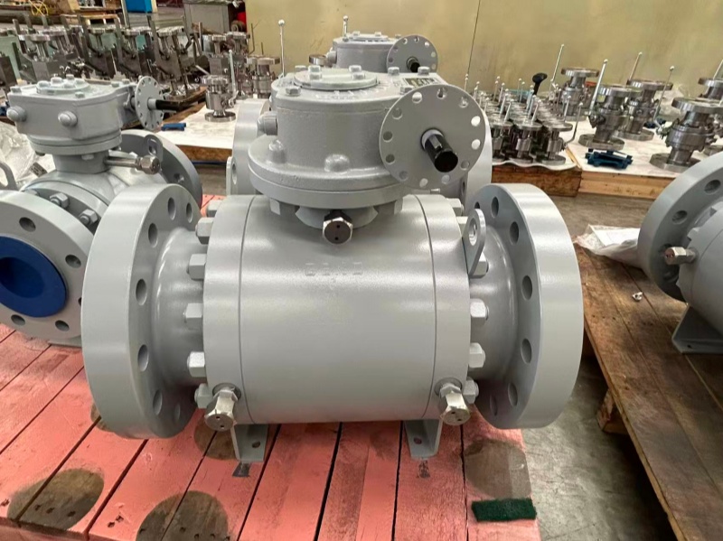
Valve Body:The body is typically made from durable materials such as 316 Stainless Steel, Monel, or Carbon Steel, depending on the application’s requirements. The robust body ensures the valve can withstand high-pressure, high-temperature, or corrosive environments.
Valve Plug:The valve plug is a critical component, typically a rotary ball or plug, that rotates to adjust the valve’s opening. This design allows for better control over flow rates compared to linear motion valves.
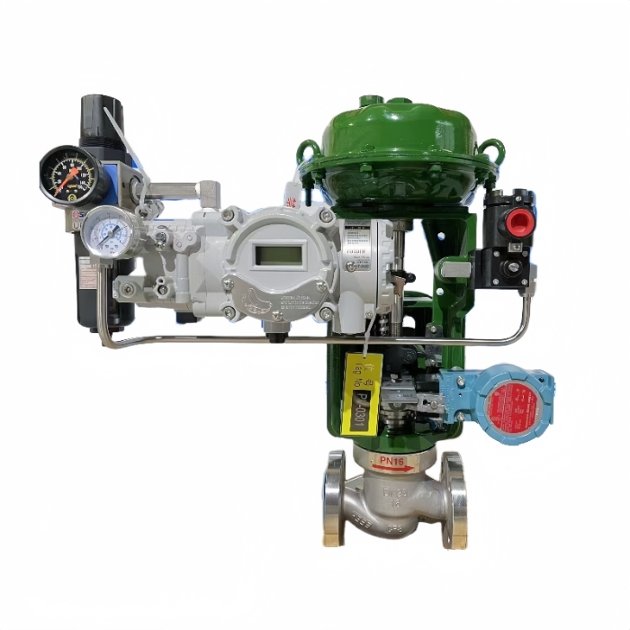
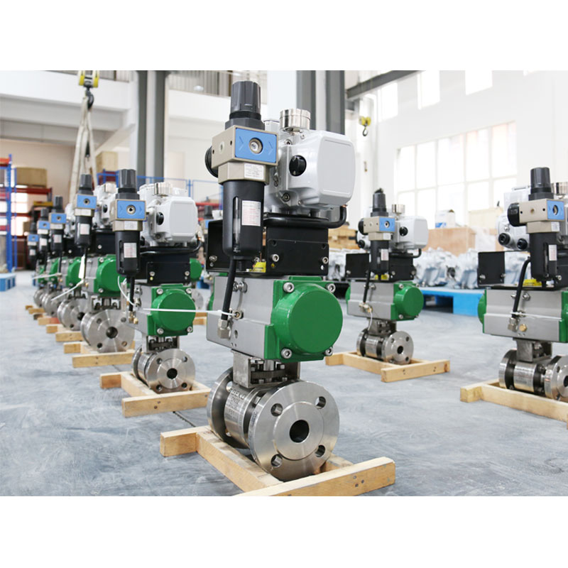
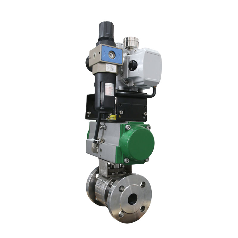
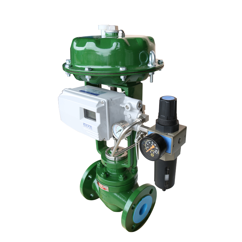
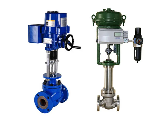
Actuator:The actuator drives the valve plug’s rotation. It can be powered either pneumatically, electrically, or hydraulically, depending on the system’s needs. The actuator’s responsive movement ensures the valve can adjust quickly to control flow accurately.
Sealing Materials:The valve uses high-quality sealing materials, such as PTFE or EPDM, to prevent leakage and maintain system pressure. These materials ensure that the valve operates efficiently and reliably over a long period.
Positioner:A positioner may be used to ensure precise positioning of the valve plug and monitor the valve’s performance in real-time.
Applications of the Rotary Globe Control Valve
The Rotary Globe Control Valve is widely used in industries that require precise control of fluid flow, especially where minimal deviation in flow rates is essential for process stability. Some of the common applications include:
Chemical Processing:In chemical plants, precise flow control is crucial for maintaining the integrity of chemical reactions. The Rotary Globe Control Valve is ideal for adjusting the flow of gases, liquids, and other reactive substances in pipelines and reactors.
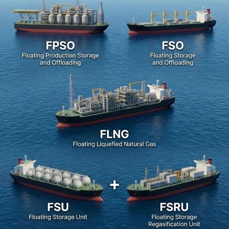
Oil & Gas:The valve is extensively used in the oil and gas industry to control the flow of oil, gas, and associated fluids through pipelines and processing equipment. The rotary design allows for efficient operation even under high-pressure conditions.
HVAC Systems:In heating, ventilation, and air conditioning (HVAC) systems, the Rotary Globe Control Valve plays a crucial role in maintaining airflow and regulating temperature. It helps maintain optimal conditions within buildings by accurately controlling the flow of air or water in heating and cooling systems.
Water Treatment:The valve is employed in water treatment plants to regulate the flow of water and chemicals used in filtration and purification processes. It ensures that the water flow remains constant, allowing for efficient treatment.
Power Generation:In power plants, the Rotary Globe Control Valve is used in steam and cooling water systems to maintain optimal flow rates, ensuring efficient energy production.
Advantages of the Rotary Globe Control Valve
Precise Control:The rotary motion provides better control over flow adjustments, making it ideal for applications where precision is critical.
Reduced Wear and Tear:The smooth, continuous rotation reduces friction, minimizing wear on the valve components and extending its lifespan.
Versatility:The valve is suitable for a wide range of applications, including high-pressure, high-temperature, and corrosive environments.
Easy Maintenance:With fewer moving parts compared to traditional linear valves, the Rotary Globe Control Valve is easier to maintain, reducing operational downtime.
The Rotary Globe Control Valve is an essential tool in industries that require precise flow regulation. Its advanced design, durable structure, and versatile applications make it an ideal solution for industries such as chemical processing, oil & gas, water treatment, and HVAC. GEKO’s Rotary Globe Control Valve delivers exceptional performance, ensuring that fluid systems operate efficiently and reliably.
Read More


 Email : info@geko-union.com
 Email : info@geko-valves.de
 Email : tw@geko-union.com
 Email : nl@geko-union.com


 IPv6 network supported