Data Center Liquid Cooling Valves: Selection, Parameters, Market, and Core Value Analysis
Feb 10, 2026
As the power density of individual cabinets exceeds 20kW, 30kW, and even higher thresholds, liquid cooling technology has become the core solution for achieving efficient heat dissipation and meeting carbon neutrality targets in high-density data centers. The piping network of a liquid cooling system is like the "blood vessels" of the system, and valves, as key control nodes, play a core role in flow regulation, pressure stabilization, and safety protection. Their design, selection, and performance directly determine the system's cooling efficiency, operational reliability, and total lifecycle cost (TCO). This article systematically analyzes the technical points and industry value of liquid cooling valves from five dimensions: the necessity of valve application, scientific selection logic, core technical parameters, market landscape data, and future development trends, drawing from hands-on experience in data center liquid cooling projects.
The Core Necessity of Liquid Cooling Valves: "Safety Guards" and "Intelligent Managers" of the Liquid Cooling System
The continuous and stable operation of a data center’s liquid cooling system relies on the precise regulation and safety protection provided by valves. Their core value spans the entire lifecycle of system design, operation management, and fault handling, specifically reflected in three core dimensions:
1. Bottom-line Guarantee for System Safety
Data center IT equipment has a zero-tolerance policy for coolant leaks. The valve's sealing performance is the first line of defense against coolant leakage and protects sensitive electronic equipment. By reasonably configuring specialized components such as safety valves and check valves, potential risks like water hammer effects and overpressure impacts can be effectively suppressed, preventing irreversible damage to server cold plates from abnormal system pressures. Given that server cold plates are typically designed for pressure resistance between 0.6-0.8 MPa, the valve must strictly control the secondary side (from CDU to cabinet/cold plate) working pressure in the range of 0.3-0.6 MPa, establishing a graded pressure protection system.
2. Precise Control of Cooling Efficiency
A liquid cooling system needs to match the coolant flow and direction with the dynamic heat load of the cabinet. GEKO valves achieve this through hydraulic balance control, which can effectively prevent localized hotspot accumulation or cooling redundancy. For instance, electric regulating valves installed at the CDU outlet receive control signals from the DCIM system to dynamically match the flow demand of individual cabinets (10-50L/min). Balance valves can compensate for resistance deviations in different pipeline sections, ensuring consistent cooling performance across all cabinets. This directly correlates to the data center's PUE value and equipment operational stability.
3. Core Support for Operational Convenience
Optimized GEKO valve configurations can significantly reduce liquid cooling system operation and maintenance costs and minimize downtime risks. Quick-connect valves support a "hot-swappable" maintenance mode for cabinets, enabling equipment maintenance without draining the coolant. Ball valves at the cabinet outlets have quick isolation functions, reducing the fault handling time of individual cabinets. Automatic vent valves and low-point drainage valves address air accumulation and impurity sedimentation issues, minimizing system fault downtime and ensuring 24/7 uninterrupted operation of the data center. Regular operational management is required: automatic vent valves need quarterly venting calibration to ensure smooth exhaust; electric regulating valves must be calibrated annually, with deviations controlled within ±1% to avoid flow distortion; seals in fluoride-based liquid systems need replacement every 3-5 years, while deionized water system seals can last 5-8 years, requiring re-testing for sealing performance after replacement.
Scientific Selection Logic: Full-dimensional Adaptation from Scenario to Requirement
The selection of liquid cooling valves should be based on functional needs, medium properties, system pressure levels, and operational scenarios, adhering to the four principles: "location adaptation, medium compatibility, precision matching, and cost control." The focus should be on covering the four key nodes of the liquid cooling system and adapting seven core types of GEKO valves.
1. Valve Configuration Scheme for Four Key Locations
- Pump Outlet Unit: Use a standardized configuration of "Gate Valve + Silent Check Valve + Pressure Sensor." The gate valve offers minimal pressure loss in the fully open state and ensures reliable isolation during pump maintenance. The silent check valve, aided by a spring structure, prevents backflow of coolant after pump shutdown and suppresses water hammer impacts on the pump impeller.
- Cooling Distribution Unit (CDU) Inlet and Outlet: On the inlet side, install a 100-200 mesh Y-type filter and a pressure gauge to remove impurity particles from the coolant and prevent microchannel blockages in servers. The outlet side should feature an electric regulating valve and flowmeter for flow-loop control. The bypass pipeline should include a manual balance valve for hydraulic balance calibration during system debugging and as a backup flow path during fault conditions.
- Cabinet Branch Piping: The inlet should be equipped with either a manual balance valve (for standard scenarios) or an automatic balance valve (for high-end computing centers). The outlet should be fitted with a ball valve to achieve quick isolation of the cabinet. The valve diameter must precisely match the cabinet's rated flow to ensure the cooling demand matches the flow capacity.
- System High and Low Points: At high points, install an automatic vent valve to expel air accumulated in the piping and prevent gas blockages and cavitation. At low points, install a ball valve or gate valve as a drainage valve for system evacuation, impurity cleaning, and maintenance tasks.
2. Seven Core GEKO Valve Types, Features, and Application Scenarios
Valve Type
Core Function
Application Scenario
Core Advantages
Ball Valve
Manual shutoff, quick isolation
Cabinet outlets, drainage pipelines
Full-bore design with minimal flow resistance, zero-leakage sealing performance
Solenoid Valve
Quick automatic on/off, safety shutoff
Branch switching, emergency shutdown circuits
Response time ≤50ms, 24VDC safe power supply, low power consumption (3-5W)
Electric Regulating Valve
Precision flow/pressure control
CDU outlet, regional control branches
Valve position control accuracy ≤±1%FS, compatible with Modbus/BACnet
Check Valve
Prevents backflow
Pump outlets, end of branches
Spring-assisted silent type effectively suppresses water hammer, opening pressure as low as 0.05bar
Balance Valve
Hydraulic balance adjustment
Cabinet inlets, regional branches
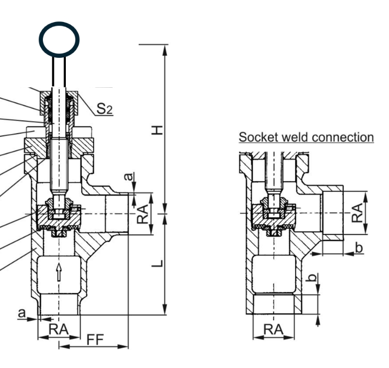
Equipped with G1/4/G3/8 pressure measurement interfaces, supports angle locking and flow calibration
Safety/Relief Valve
Overpressure protection, pressure release
Main pipeline, CDU unit
Set pressure accuracy ±3%, meets ASME BPVC Section VIII or PED certification
Quick Connect Valve
Hot-swappable maintenance, quick connection
Cabinet inlet/outlet
Maintenance without draining the system, high sealing reliability, standard for high-density environments
3. Material Selection Core Principles: Medium Compatibility First
Valve material compatibility with coolant is key to ensuring long-term stable operation. Corrosion of materials, swelling of seals, and impurity precipitation must be avoided. The material adaptation plan for different cooling mediums is as follows:
- Deionized Water: The valve body should be made of 304/316 stainless steel, and seals should be EPDM or fluororubber. Brass material must be avoided to prevent zinc element precipitation and contamination of the coolant.
- Ethylene Glycol Solution: The valve body should be made of 316 stainless steel to enhance corrosion resistance, and seals should be nitrile rubber or fluororubber, with a focus on sealing reliability under low-temperature conditions.
- Insulating Fluorinated Liquids: The valve body should be made of 316 stainless steel or carbon steel coated with nickel, and seals should be fluororubber or perfluoroether rubber (FFKM), with a 72-hour compatibility soaking test before use.
- Mineral Oils: The valve body can be made of carbon steel or stainless steel, with seals adapted to fluororubber or PTFE, considering the impact of the medium’s expansion coefficient on seal performance.
4. Common Selection Pitfalls and Key Avoidance Points
In practical engineering, valve selection is prone to misunderstandings. Key issues to avoid include:
- Confusing "working pressure" with "design pressure," selecting valves based solely on working pressure leads to insufficient pressure margin. Selection should strictly be based on design pressure (working pressure ×1.1-1.2 safety factor).
- Ignoring long-term compatibility between seals and fluorinated liquids, using only short-term tests before use. Suppliers should provide third-party 72-hour immersion test reports to verify no swelling or aging.
- Not providing measurement interfaces on balance valves, making it impossible to accurately quantify hydraulic adjustments in later stages. Ensure that G1/4 or G3/8 standard pressure measurement interfaces are included in the selection.
- Blindly pursuing "all imported" valves, ignoring the benchmark cases of domestic brands. For retrofit projects, prioritize selecting domestic brands with experience in North American or Middle Eastern projects to balance cost and reliability.
Core Technical Parameters: Key Indicators Determining Valve Performance
Data center liquid cooling valves require more stringent control accuracy and operational reliability than those used in traditional HVAC or oil and gas sectors. They must meet the data center's Tier level and long-term operational needs, with key indicators classified into two categories: General Core Parameters and Specialized Parameters.
1. General Core Parameters (Essential for All Valve Types)
- Leak Rate: External leakage must meet zero-tolerance standards, with a helium mass spectrometer leak rate of <1×10⁻⁹ Pa·m³/s. Internal leakage for shutoff valves must meet ANSI Class VI or higher, with no detectable leakage in fluoride liquid or ultrapure water systems.
- Pressure Endurance: Working pressure must cover the system’s design pressure (typically 0.5-6bar), with a 1.5-2x safety margin. The system's design pressure generally does not exceed 1.6 MPa, and the valve must withstand transient high pressures (water hammer conditions) at 1.3-1.5x.
- Reliability and Lifetime: The Mean Time Between Failures (MTBF) should match the data center's 10-year lifespan requirement, with mechanical cycling for electric and solenoid valves not less than 100,000 times. Actuator protection level should be no lower than IP65, and IP66/IP67 for extreme humid environments.
- Cleanliness: The internal pipeline must be smooth with no dead spots. The system should undergo precision cleaning before shipment, with particulate cleanliness reaching NAS 1638 Class 6 or higher to prevent microchannel blockages in servers.
- Operating Temperature: The valve should adapt to a standard operating range of 5℃-60℃ for liquid cooling systems, with support for temperatures up to 80℃ or higher in high-temperature return scenarios.
2. Specialized Parameters (Type-specific Core Requirements)
- Electric Regulating Valve: Should support 0-10V DC/4-20mA analog control signals and can be equipped with Modbus, BACnet, and other digital communication protocols. The Kv value must be precisely calculated based on design flow and allowable pressure drop.
- Solenoid Valve: Powered by 24VDC safe voltage, with fail-safe positions in normally closed (NC) or normally open (NO) mode. Response time ≤50ms and compliance with UL, CE, RoHS certifications.
- Balance Valve: Equipped with G1/4 or G3/8 standard measurement interfaces. The manufacturer must provide a third-party calibrated opening-KV value curve and locking functionality to prevent misoperation affecting hydraulic balance.
- Safety Valve: Set pressure should be 1.1-1.2 times the system's maximum working pressure, with release capacity equal to or greater than the pump unit's maximum output flow. It must meet ASME BPVC Section VIII (US standard) or PED 2014/68/EU (EU standard) certification.
3. Testing and Acceptance Standards
Valves must undergo rigorous testing and acceptance procedures to ensure they meet engineering requirements. The core processes and standards are as follows:
1. Factory Testing: The strength test pressure should be 1.5 times the design pressure. The valve should be pressure-hold for 30 minutes with no leakage or deformation. The sealing test uses helium mass spectrometer leak detection, with a leak rate of <1×10⁻⁹ Pa·m³/s.
2. On-site Acceptance: Verify valve model, material, certification documents, and design consistency. For key valves, perform sealing re-checks, and test electric valves for control signal response and valve position accuracy.
3. System Integration and Acceptance: Verify the reliability of valve interaction with the DCIM system. Safety valves must be calibrated on-site to ensure timely pressure release during overpressure conditions.
Future Trends: Accelerating Intelligence, Standardization, and Domestic Substitution
1. Technical Trends: Intelligent and Modular Upgrades
Liquid cooling valves are upgrading towards digitization and modularity, with the following core trends:
- Intelligent Integration: By embedding sensors and communication modules, valves enable real-time monitoring of valve status, fault warning, and remote control, deeply integrated into the DCIM management system.
- Modular Design: Simplifying system integration and expansion processes. Quick-connect valves have become standard in high-density data centers.
- Core Component Upgrades: Actuators are evolving towards low power consumption and high protection ratings. Chip and control algorithm autonomy has become the core competitiveness for companies.
Read More


 Email : info@geko-union.com
 Email : info@geko-valves.de
 Email : tw@geko-union.com
 Email : nl@geko-union.com


 IPv6 network supported