What Are You Looking For?
INTRODUCTION
|
ASME Classes |
Sizes |
Body Style |
|
150, 300, 600, |
1" - 36" |
Flanged, Butt Weld |
|
900, 1500, |
25.4mm - 915mm |
Socket Weld, Ring Joint, |
|
2500, 4500 |
Grayloc |
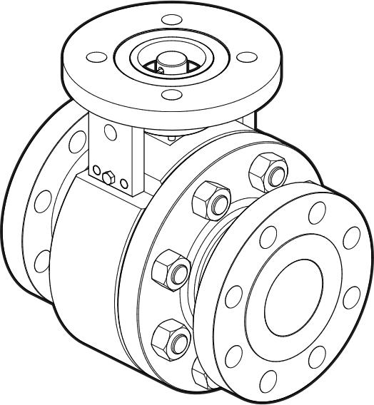
The Series metal seated severe service ball valve is designed in accordance with ASME B16.34 and ASME .The Series is designed as a free floating ball valve with metal seats. It is important to install the valve in the pipe as intended to achieve optimal performance. If there are any questions,
please contact us. info@geko-union.com

The Series can be configured for unidirectional or
bidirectional flow. The preferred flow direction and high pressure side is indicated on the valve. Proper attention must be paid to ensure that the valve is installed according to the preferred flow direction and designated high pressure side.
The preferred flow direction is indicated on the nameplate or valve.
The severe service ball valve is designed to handle entrained solids and the corresponding abrasive/erosive conditions that are associated with such applications. Depending upon the specific application, the M1 may be equipped with purge port and/or
flushing ports in order to flush particulates from the body cavity, prevent scaling, or remove accumulated media. Please refer to
the trim of your specific product for the corresponding seat
design and presence of such ports. Proper trim and maintenance greatly extends the life of the valve in these harsh environments
Special Conditions for Safe Use
The following factors must be carefully considered in order to
ensure the valve is compatible with the atmosphere in which it is applied. The system designer and/or end user should formally address each severe service ball valve and carefully document
the reasoning behind specific measures taken to ensure
continued compliance throughout the life of the severe service ball valve.
Material Considerations
Titanium is not to be used in Group I mining applications and Group II Category 1 equipment, due to the potential of ignition from sparks caused by mechanical impacts. Please consult
factory for details regarding material limitations
Temperature Considerations
The Series severe service ball valves are designed in accordance
with ASME B16.34 pressure/temperature ratings and are
suitable for operating temperatures up to 593 °C (1,100°F),
depending on the materials of construction. Custom designs are available upon request and the pressure and temperature ratings will be marked on the valve tagging. Service media should be
considered when evaluating pressure and temperature ratings.
The system designer is responsible for ensuring the maximum temperature, either inside the valve body or on the external
surface, will remain well below the ignition temperature of the atmosphere. Additional protective devices may be required
to ensure a sufficient thermal safety margin including but not limited to: thermal shut off devices and cooling devices.
For operating temperatures above 200°C (392°F) Bray recommends thermal insulation of the valve body.
Static Electricity Considerations
Where the process medium is a liquid or semi-solid material with a surface resistance in excess of 1 G-ohms, special precautions
should betaken to ensure the process does not generate
electrostatic discharge. This may be done through ensuring the flow rate of the process media remains below 1 m/s or providing sufficient discharge points along the process path to eliminate
electrostatic buildup.
Appropriate grounding may be necessary through the use of grounding straps or other means.
Stray Electric Current Considerations
When the severe service ball valve is used near sources of high current or magnetic radiation, a secure bonding to earth ground should be made so as to prevent ignition due to inductive
currents or a rise in temperature due to these currents.
Entrained Solids & Process Media
Special consideration should be made regarding the filtration of the process medium if there is a potential for the process
medium to contain solid particulates. The process medium is recommended to be filtered to allow particles no greater than 1.0 mm in diameter through the valve assembly where there
is a high probability of solid particulates. Larger particulate
sizes may be deemed appropriate based on the possibility
of particulates within the process medium and the area
classification. The decision regarding filtration levels and limits
should be well documented by the system designer and/or end user to ensure continued compliance through the life of the
valve.
HAZARD FREE USE
This device left the factory in proper condition to be safely
installed and operated in a hazard free manner. The notes and warnings in this document must be observed by the user if this safe condition is to be maintained and hazard free operation of the device assured.
Take all necessary precautions to prevent damage to the valve
due to rough handling, impact, or improper storage. Do not use abrasive compounds to clean the valve, or scrape metal surfaces with any objects.
The control systems in which the valve is installed must have
proper safeguards — to prevent injury to personnel, or damage to equipment — should failure of system components occur.
The upper limits of permitted pressure and temperature
(depending on the valves materials of construction) must be
observed. These limits are shown on the valve identification tag.
The valve must not be operated until the following documents have been observed:
> Declaration on EU Directives
> IOM Manual (supplied with the product).
